From BMM and TOGAF toward SOA - Capitalizing on the Business Capabilities
BRIDGING BUSINESS GOALS, CAPABILITIES, PROCESSES WITH THE IT LEVEL SOA COMPONENTS
Abstract
The Goal-Driven and Business Capability based SOA Framework described in this presentation aims at providing organizations with a content framework that helps to increase competitiveness by capitalizing on their business capabilities (1) as well as synchronizing IT system components with evolutions of their goals and underlying structures.
It makes reference to the elements of the TOGAF 9.1 Content Metamodel, those of the OMG's Business Architecture Views and the Business Motivation Model (BMM) (2) to allow SOA based IT system components to evolve coherently according to strategic and tactical changes.
Even though TOGAF's ADM phases are not part of the focus of this article, architectural descriptions that accompany this presentation make reference to the TOGAF 9.1 and Archimate 2.0 Business Architecture and Information System Architecture layer elements and complete them with a Goal-Driven SOA approach.
Examples that are given there provide also some illustrations about the refinement of Architecture Building Blocks (ABBs) until the plugging of Solution Building Blocks (SBBs) into the SOA architecture backbone on the basis of the business capabilities.
(1) Business Capability : A particular ability or capacity that a business may possess or exchange to achieve a specific purpose or outcome. A business capability describes what the business does (outcomes and service levels) that creates value for customers - [Business-Oriented Foundation].
(2) The Business Motivation Model [BMM] - Business Governance in a Volatile World voted by the OMG in 2007.
1 Introduction : wHY DO SOA COMPONENTS NEED TO BE BASED ON TOGAF busIness capabIlItIes AND THE BUSINESS ARCHITECTURE VIEWS ?
Since the last few years, most of the emerging SOA development methodologies (including the Open Group's TOGAF for SOA) do not consider clearly business capabilities in the process of identification of business and IS services.
Moreover, despite playing a central role in the TOGAF 9 ADM method, capabilities are not referenced in the ArchiMate 2.0 language metamodels [ArchiMate 2.0 Specification] which are normally designed to complete formally the lack of traceability and consistency issues between the ADM phases elements.
Being totally disconnected from business goals and capabilities, the resulting IT system suffers from agility issues in aligning service descriptions to changing business decisions.
On the other side, it is difficult to capitalize on business processes to align IT applications with changing business decisions, as business processes evolve frequently in time.
Therfore, we need to look for more stable elements that are the "business capabilities" of the organization - capacities that a company should possess or exchange to support its vision. A business capability describes what the business does (outcomes and service levels) that creates value for the organization and its customers.
The concept of business capability is also referenced within the TOGAF 9.1 Architecture Content MetaModel [TOGAF 9.1] but without any formal link toward business functions, processes, services or IT layer components.
Indeed, the Capability element of the metamodel illustrated below needs to be directly linked to the Motivation Extension (Driver, Goal, Objective) elements to be able to measure direct impacts of strategical changes on the business capabilities of the organization.
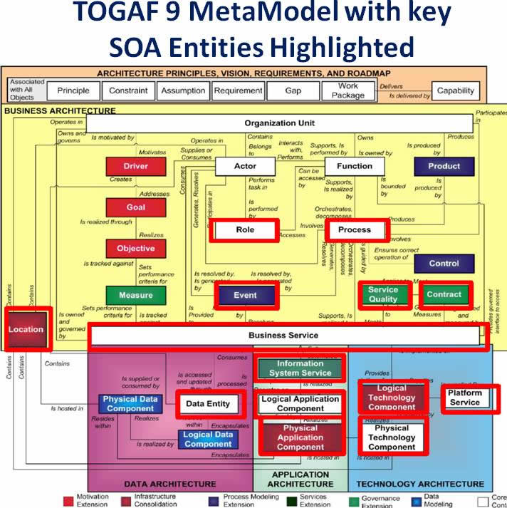
In TOGAF SOA Entities Content MetaModel [TOGAF 9.1], the Motivation Extension (Driver, Goal, Objective) elements need also to be linked to Business Capabilities and Functions to align business and IT system components with strategic changes
Other complementary information about the links between business strategies and capabilities are provided in the the Business Architecture Views of the OMG's Business Architecture Working Group.
As illustrated below, the business architecture views are being there supervized by the business strategy view that captures tactical and strategic goals of the organization.
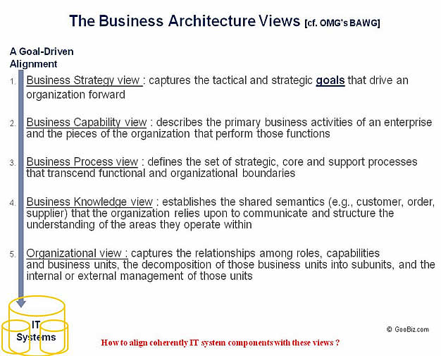
Figure 1 : An Inherent Goal-Driven Alignment from the Business Strategy View toward the Organizational View of the OMG's Business Architecture Working Group
Finally, in order to align IT system components to changes on the business strategies, capabilities need to be modeled as "reusable and reconfigurable objects". Such a modeling should allow stakeholders to capitalize on them in face of changes.
This means that after having expressed capabilities as groups of business functions like Marketing, Sales, Product Management, Tele-Marketing, etc...as part of the 1st. level capabilities of a business capability cartography, we need to continue their decomposition until modeling them using component of business objects in states.
Using such an object-in-state modeling of the capabilities, the responsibility assigned to each capability component is expressed by a 'desired state' that expresses the goal to be reached on the corresponding object and made 'actionable' as depicted on figure 3 below.
The example shown below illustrates a small number of 2nd level capability components of a WebSale Company. These components are obtained after decomposition of a 1st. level capabilities that may be constitued of business functions like Product Management, Visitor Management, Customer Management and Order Management.
On the basis of the previous OMG's BAWG Business Architecture Views, the business strategy view is represented there by the enterprise vision component which is supported by the business capabilities.
The Process View that realizes some of these business capabilities will be shown next within their own organizational units (organizational view).
Enterprise Business Objects and their relationships illustrated at the bottom side of the schema are part of the business knowledge view.
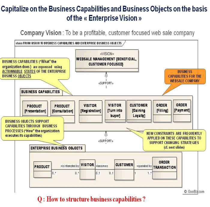
Figure 2 : An example on the OMG's Business Architecture capability and knowledge views expressed respectively using business entities, desired states and relationships
STRUCTURING BUSINESS CAPABILITIES TO ALIGN SOA COMPONENTS
According to TOGAF 9.1 MetaModel, business functions are designed to "deliver" business capabilities and each business function is bounded by a business service that provides a governed interface to access that business function.
This means capability components that we have modeled above are supported by a set of underlying business functions that collaborate to deliver the business value expected from the capability (in realizing its associated goal). Also, in order to realize that goal, business functions that are part of each capability are to be orchestrated by a business function whose access is governed by its corresponding business service.
Such a goal-driven business service (GDBS) orchestrates the delivery of the "value" associated to a business capability in respect to business service levels expected from its business functions. In order to establish the bridge toward SOA components, business functions that are part of a capability component may be considered there as its service/request points « SRV-Ps».
The figure below shows the Actionable Visitor [Registration] Capability Orchestrator with its parts, requirements. and potential service level expectations.
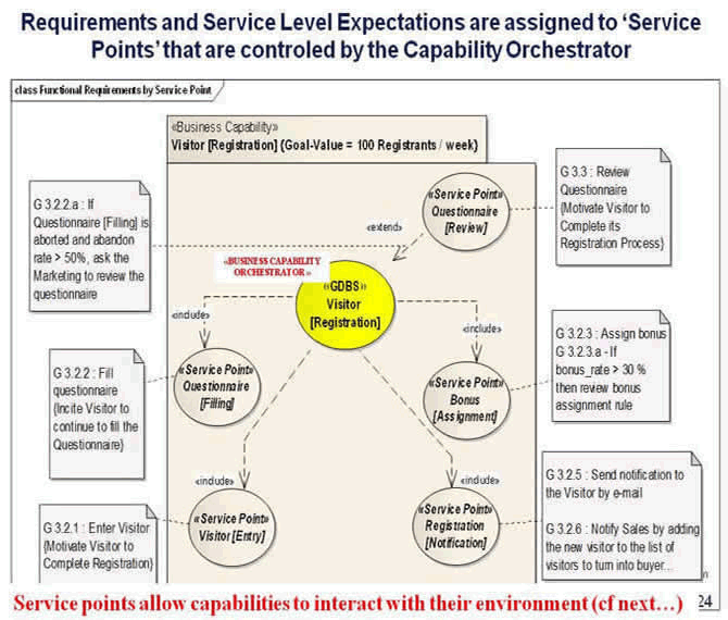
Figure 3 : Internal structure of a business capability component with its orchestrator service (GDBS), orchestrated service points (SRV-Ps) and expected behaviors to realize its associated business value
Notice : Orchestrating business functions under related business capabilities help us to understand how to reconfigure such capabilities in order to better 'serve' the "stages of the value stream" that need to be re-aligned with the changing strategies and tactics.
At the system layer, we will also introduce the concept of Goal-Driven Service (GdS) as a specialization of the GDBS in order to complete its behaviors by considering the usage constraints of its users at the functional (system) layer.
Goal-Driven Process Modeling to Capitalize on the Business Capabilities
In order to capitalize on the business capabilities by reusing them when dealing with changes on strategies, we expressed business capabilities, their orchestrator and service points using goal-oriented objects (business objects expressed within states to execute required behaviors to realize their goal).
Such a representation allows us to bring extensions to behaviours already assigned to capabilities just by applying new constraints on their existing states (see figure 4 below).
As a result, business processes that realize services exposed by capabilities have to be reconfigured according to these changes.
The figure below shows changes requested from a business capability by the constraints {Goal-Value = 100 registrants/week} imposed to its orchestrator (represented in yellow) and potential impacts on the activities of the process that supports its realization.
Process activities that have to be changed in respect to these constraints are indicated by elliptic shapes. All other activities are reused with their existing behaviors.
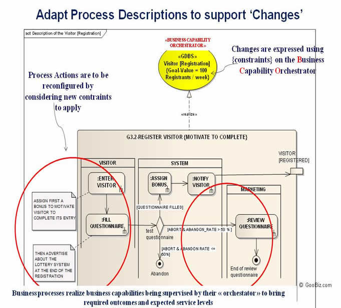
Figure 4 : A description of the Process that realizes the Visitor [Registration] Capability with constraints applied only to some of its activities
Finally, such a "goal-driven tracking" operated on the business processes helps us to :
- realize a goal-based traceability and impact analysis in face of changes on the business capabilities,
- reconfigure appropriate activities of business processes according to these changes by re-using all other activities of the process.
Business Capability Components within the Business and IT Layers of the SOA
Behaviors of a capability orchestrator (GDBS) defined at the business layer can be extended by a Goal-Driven Service (GdS) at the functional layer by considering application choices of their users.
This means that additional application level usage scenarios may be required from a capability orchestrator at the functional layer as IT users may request to use it by making some changes to them while respecting its original business constraints - cf. : Pattern for using Business Behaviours from the Application Layer.
The diagram below shows service and use case components as well as their realization scenarios into the Business and Information System Architecture layers.
Actions of Service Points (SRV-P in the figure) may be initiated when they are invoked by their orchestrator -Goal-Driven Service (GdS). Once initiated, each Service Point may interact with the corresponding use case components in situations where an actor interaction is necessary.
For example, in order to realize the function Enter Visitor , the service-point Visitor[Entry] needs to interact with the use case component Enter Visitor.
Business Capability orchestrators (as well as their IT layer extension) also help us to discover entity objects they have to handle via their service point operations. For instance, in the figure below, the orchestrator of the GdS Visitor [Registration] may help us to discover entity objects such as Visitor, Marketing, Sales etc,...on the basis of requirements that are supported by its operations.
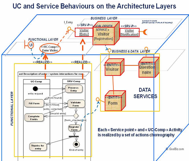
Figure 5 : A hierarchical view of a business capability component across the business and IT layers and interactions with its environment (use cases components, user interfaces and data services)
Integrating the Business Motivation Model (BMM) within the SOA Framework
Finally, in order to better react to changes at the business level decisions, the Goal-Driven SOA framework has to integrate the core elements of the BMM and provide traceability support from business motivation elements (vision, goals, strategies, tactics, policies, etc...) toward IT system components on the basis of the business capabilities.
In the figure below, dashed circles indicate the core elements of the BMM that are considered as primary for bridging BMM to SOA. As shown in the figure, business goals as part of the ends drive strategy and tactic, rules and policies till business processes.
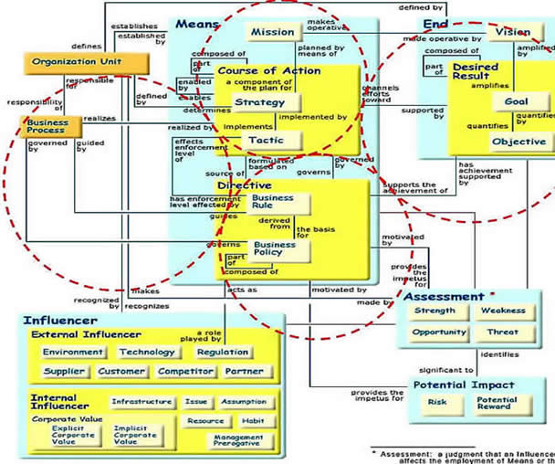
Figure 6 : The Business Motivation Model for the Business Governance in a Volatile World [BMM] of the Business Rules Group first voted by the OMG in September 2005
The Business Motivation Model addresses especially the business Owner's perspective (i.e., row two) of the sixth aspect (i.e., the Motivation or 'Why' column) of the Zachman's Enterprise Architecture Framework [BMM 2007].
As the IT architecture needs to closely reflect the business goals and be based on the business capabilities to capitalize on the business knowledge of the organization, it becomes necessary for the Goal-Driven SOA framework to structure IT systems on the basis of this goal-driven and capability based alignment.
This way, we can distinguish the following abstraction layers in this framework to establish a bridge from the business architecture views of a Business Model toward IT architecture components of an Enterprise SOA Operating Model to carry out business needs and trace impacts of changes until the software level :
:
- The Business Motivation Layer (the "Why") : to reconfigure business processes and responsibilities of their participants according to changes captured at the business layer (strategic, tactical or rule based changes to support desired results),
- The Functional Service Definition Layer (the "What") : to determine impacts of the previous changes on the IT level system components (services that are derived from processes and capabilities, use cases and entity objects) as well as on system requirements that implement business rules,
- The Application Layer (the "Technical How") : to describe realization of functional specifications from the application presentation layer (user interfaces) to the persistance layer (database entities) within the architecture,
- The Deployment Layer (the "Where"): to describe location of the technical components starting by their high-level descriptions like agencies, headquarters, front and back offices, etc.. until physical nodes of the architecture where they should be deployed.
In this perspective, the section below explains elements of the Goal-Driven Development Framework as well as their relationships from the business goals through the software implementation level.
2 LINKS FROM THE BUSINESS MODEL to ENTERPRISE SOA OPERATING MODEL ELEMENTS
In order to bridge business decisions toward IT system behaviors, the layered architecture meta-model introduced below focuses on establishing links from the Business Model (business motivation model) to an Enterprise SOA Operating Model. It allows IT alignment of the Functional and Application layers according to the Business Motivation (the "Why") layer decisions.
Inside the Business Motivation Layer (the "Why"), the main focused elements are Goal (END), Strategy, Tactic (MEANS), Business Rule ( DIRECTIVE), Business Capabilities, Business Processes and Resources.
The Functional Service Definition Layer (the "What") focuses on identifying services of the system and use cases that are candidate to invoke them as well as resources that are to be handled by services at this abstraction level.
The Functional Service Description and Realization level (the "Functional How") is about detailed specifications of services and use cases. Then it focuses on actions that realize behaviors of these components from the User Interface toward Entity Objects.
The Application Layer (the "Technical How") focuses on the technical specifications of services and use cases to implement the Goal-Driven SOA backbone. In this context, it focuses on the plug-in of technical components to realize behaviors of functional elements from the User Interface toward Database entities.
Finally, the Deployment Layer ("the Where") describes the physical deployment of the technical components.
Along this refinement process, requirements that are discovered on the basis of the Business Motivation Layer are used and enriched by the Functional (Service Definition) and Application (Realization) layers.
The schema below shows an overview on the main elements of these abstraction levels. Details about the top down traceability relationships between these levels are presented next.
Notice : According to the Business Capabilities view of the OMG's BAWG that describes the primary business activities
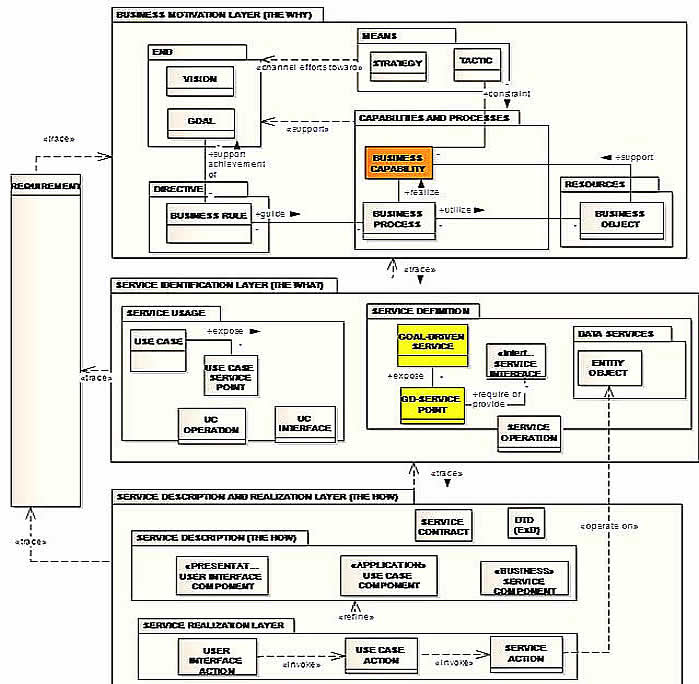
Figure 7: Overview on the essential elements of the business, functional and IT service realization layers to bridge the BMM to SOA. The internal structure of the Business Capability Component (the GDBS and Service Points) are shown in figure 3
In the next paragraph, we introduce traceability relationships between elements of these abstraction layers. To better help to understand the meaning of each element, we show them by giving examples of the case study attached to these elements.
2.1 relationships INSIDE the BUSINESS MOTIVATION LAYER - MOTIVATION Extensions FOR TOGAF's BUSINESS ARCHITECTURE PHASE B (The "why")
Inside this layer, we focus on the core elements of the BMM that permit to describe business processes being guided by goals, rules and tactics.
On the basis of the business vision of our case study that is "To be a profitable customer focused websale company", the main goal of the business is given up as "To build a Beneficial WebSite System". A strategy that channel efforts toward that goal is set to "Turning visitors into Buyers".
Two first tactics are discovered in order to implement this strategy. These are indicated by G3- Motivate internet visitors to Register using a Bonus System" and G2 - Encourage Sales Employees to turn Visitors into Buyers".
Tactics impose constraints to the business capabilities that can be breakdown for organizational reasons.
For instance, the tactic "Motivate Visitors to Register" may apply contraints to the business capabilities such as Product Presentation and Visitor Registration, thus to let them reconfigure their corresponding processes.
At the bottom part of the model, directives (policies or business rules) support achievement of business goals.
A business rule is a statement that defines or constrains some aspects of the business [Business Rules]. In the context of the Business Motivation Layer, business rules provide the tactical detail about how exactly a strategy will translate to actions then guide business processes.
A policy is composed of directive elements, each of them can be an underlying policy or a business rule. In the example below, the policy "Marketing Staff to keep Visitors on the WebSite ..." aggregates two essential business rules that respectively are about the Abandon rate of Visitors within the Product Consultation (BR1.a) and Registration Processes (BR2.a).
Finally, in order to realize business capabilities that are constrained by tactical changes, business processes are appropriately designed.
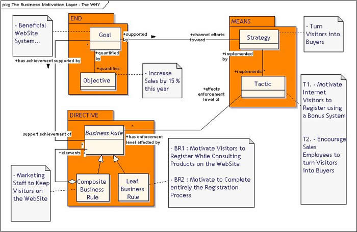
Figure 8 : Elements of the Business Motivation Layer and their relationships to govern the bridge toward the SOA service definition layer. Business functions that deliver business capabilities (cf. TOGAF Content MetaModel above) are considered as part of these capability components. Business processes that realize these capabilities manage activities and actions that compose them. An action may be a human task or an automated action.
2.2 LINKS TOWARD THE INFORMATION SYSTEM (I.S) ARCHITECTURE TO DEFINE " IT SERVICES" , USE CASES, UI, ENTITIES,...
As stated above, behaviors of a business capability orchestator (GDBS) defined at the business layer are traced by a Goal-Driven Service (GdS) at the functional system layer to consider application choices of users.
In this perspective, we have illustrated (cf figure 5) how use cases, service points and related user interface components as well as entities should interact to support realization of a GdS. These links are shown at the figure below.
Use Case Identification
Use Cases components are identified according to responsibilities assigned to the participants of a business process. Then, they are described to support actor / system interactions necessary to realize a GdS or behaviors requested from a service point (SRV-P).
In the figure below, use case components are illustrated via "Use Case Service Points" that are exposed by Use Cases.
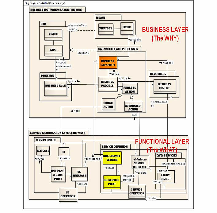
Figure 9 : Links between the Business Motivation Layer (the WHY) and the Service Identification / Usage Layer (the WHAT)
Goal-driven services carry out strategic and tactical constraints they receive from business capabilities and transmit them to their service/request points « SRV-P » and corresponding use case components.
In this context, they handle processing of related exceptions, SLA (Service Level Agreement) constraints and can easily provide inputs to feed-back mechanisms supported by the BAM (Business Activity Monitoring) tools.
2.3 INTERNAL LINKs inside the INFORMATION SYSTEM architecture - TOward the SERVICE description AND REALIZATION LAYER
The main role of the service description and realization layer is to give a description of appropriate goal-driven services and use cases identified at the business motivation layer then explain how to realize them.
Goal-Driven Services that are identified previously according to Business Capabilities and their tactic based evolutions as well as Use Cases that are determined at the Service Definition Layer (The What) are traced and detailed at the Service Description Layer (the how) respectively by the corresponding descriptions.
UC and Service Operations are described there by the corresponding scenarios.
For instance, operations like Enter Visitor, Fill Questionnaire and Notify Visitor... that may be potentially exposed by the service point Visitor [Entry] are to be described at this layer by the corresponding scenarios.
Same things apply for the description of use case operations..
Service Contracts and Exchanged Data between service operations (see figure above) are also described there.
The paragraph below shows relationships inside the service description layer.
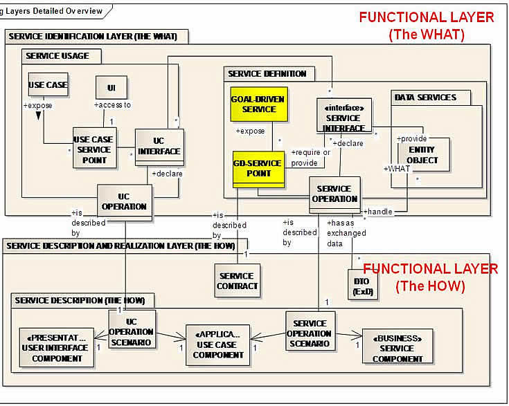
Figure 10 : Links from Service Definition / Usage Layer (the WHAT) toward Service Description Layer (the HOW)
2.4 INTERNAL LINKs inside the Information System architecture - THE SERVICE DESCRIPTION AND REALIZATION LAYER
The purpose of the Service Realization sub-layer is to describe how to achieve service and use case scenarios of the Service Description Layer using components of a logical IT architecture ( Presentation, Application, Business Service and Domain Object Layers).
Actions of the service description layer are described there using collaborations between these logical components.
Each logical component orchestrate their own underlying actions described in the service realization layer.
For instance, connections illustrated in figure 11 below can allow us to realize the Enter Visitor scenario using actions of the presentation, use case and service logical components as shown below.
These actions may be identified using an activity diagram that illustrate collaborations between actions of each logical layer (see figure 13).
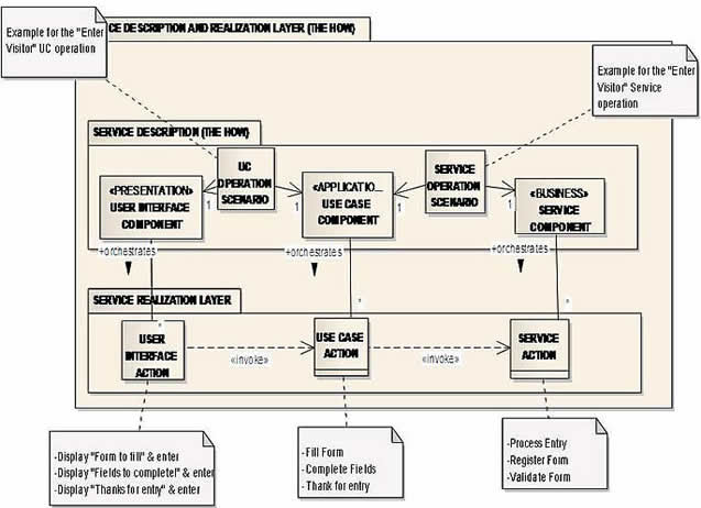
Figure 11 : Relationships inside the Service Description and Realization Layer (the Functional HOW)
An illustration of interactions between GUI, Use Case and Service Components to materialize the Enter Visitor scenario according to these relatioships may be described at the Implementation Governance Phase (phase G) of TOGAF 9 (figure 13).
2.5 AN OVERVIEW within the iNFORMATION SYSTEM ARCHITECTURE LAYER : FROM BUSINESS CAPABILITIES TO SOA COMPONENTS
Application layer components that realize functional specifications described in the service description layer constitute the bottom part of the Goal-Driven Service Oriented Architecture backbone.
An hierarchical traceability of constraints from business capabilities toward Architecture Building Blocks (ABBs) are illustrated in the figure below.
Software components UC-Cmp and SRV_Cmp that are to be plugged into the ABBs give examples of black box Solution Building Blocks (SBBs) that may be considered in phase E (Opportunites and Solution) and implemented in phase G.
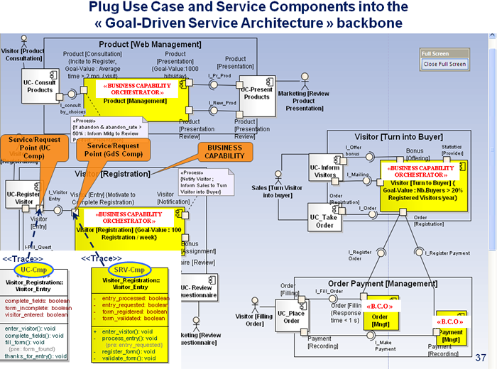
Figure 12 : Solution Building Blocks (SBBs) like the UC-Cmp and SRV-Cmp software components are considered to be plugged into their respective parent Architecture Building Blocks (ABBs) within the goal-driven architectural backbone of the system
2.6 IMPLEMENTATION OF SOLUTION BUILDING BLOCKS (SBB) in THE IMPLEMENTATION GOVERNANCE phase (PHASE G)
According to the paragraph 2.4, an example of specification is given below.
From left to right, screens and UI actions of the GUI Presentation interact with actions of the Use Case Components (UC-Comp) and finally with actions of the Service Point (SRV-Comp) to "Enter Visitor".
Use Case actions operate on graphical user interfaces (GUI) whereas Service actions operate on entity objects, most of the time by changing their states.
Components depicted at the bottom part of the figure below illustrate UC and Service Components with their operations generated on the basis of the corresponding actions shown in the swimlanes of the activity diagram.
They are plugged into the SOA backbone in order to test their correct integration with the existing components of the backbone (as shown in the previous figure).
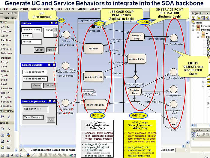
Figure 13 : Interactions defined at the Functional Service Realization Layer between GUI, Use Case and Service components to Enter Visitor
3 CONCLUSION
The Goal-Driven and Business Capability based SOA Framework illustrated in this presentation is intended to increase business competitiveness of organizations by aligning their IT systems with evolutions of their business goals and capabilities.
In this perspective, the layered architecture elements and their inter-relationships of the "Goal-Driven SOA" Framework allowed us to understand how to structure business capabilities and connect them with the business motivation elements of BMM to 'synchronize' SOA components with changes on business decisions.
An enhanced animated version of this article that illustrates traceability from the Balanced Score Cards (BSC) perspectives till implementation using TOGAF and ArchiMate may be downloaded by clicking on the second link available on :
From Business Capabilities to SOA - TOGAF 9.1 and Archimate 2.0 using Sparx
Notice : An earlier version of this article entitled "From The Business Motivation Model (BMM) To Service Oriented Architecture (SOA)" is available on the Journal of Object Technology, vol. 7, no. 8, November-December, pp. 57-70
4 REFERENCES
[Archimate 2.0] : http://pubs.opengroup.org/architecture/archimate2-doc/
[Business Capabilities] : http://msdn.microsoft.com/en-us/library/aa479368.aspx#servorient_topic3
[Business Capabilities View] : The OMG's Business Architecture Working Group http://bawg.omg.org/business_architecture_overview.htm
[Business-Oriented Foundation] : Ulrich Homann - MSDN - http://msdn.microsoft.com/en-us/library/aa479368.aspx#servorient_topic3
[BMM 2007] : The Business Motivation Model - September 2007
[Business Rule ] : Defining Business Rules
[Running Business on your Goals and Directives] http://www.goobiz.com/RunningBusinessOnTheGoals.htm
[SoaML] : http://www.omg.org/docs/ad/08-08-04.pdf
[TOGAF 9.1] : http://pubs.opengroup.org/architecture/togaf9-doc/arch/chap34.html#tag_34_02_01
[TOGAF for SOA] : http://www.opengroup.org/soa/source-book/togaf/entsoa.htm
BMM is currently used in the following 'Digital Model Innovation' and the NATO NAF v4 Framework standards :
- BMM in The 'Digital Model Innovation' : Enabling End-to-End Value Creation for a Better Customer Journey...
- BMM in NAF v4 : The Unified Architecture Framework (UAF / UPDM 3) in the Context of the NATO Architecture Framework Version 4
Birol Berkem, Ph.D - GooBiz