GooBiz is a consultancy and training company specialized in the domains of the Enterprise and MBSE Architectures such as TOGAF, DODAF, MODAF, UAF/UPDM, NATO NAF as well as modeling languages like SysML and ArchiMate. We provide services across NA, EMEA (and currenty all other locations including Asia-Pacific in distance training)
mailto : info@goobiz.com
Duration :3 days
for more information, please mail to : info@goobiz.com
3 days Total Training Cost
-Online Remote Session up to 4 participants : 3300 €
-Online Remote Session with 5 to 8 participants : 4200 €
System Engineering using SysML and MBSE standards
Requirement Gathering, System Analysis and System Design using SysML and MBSE standards ( UPDM, UAF, NATO NAF, ...)
System Engineering using SysML and MBSE Standards (3 days)
Objective : Helping Analysts and Designers of the System Engineering domain understand how to efficiently gather requirements then go through the system analysis and design using Model Based System Engineering (MBSE) methodologies and the OMG's SysML - System Engineering Modeling Language.
This 3 days training aims at assisting system engineers to understand how to gather efficiently business and engineering requirements of a product and make the appropriate architectural design of the system.
The resulting system architecture should also provide a good level of agility in face of changes as it allows a coherent identification and traceability of functionalities encapsulated within system components until the implementation.
Prerequisites : Previous experience in System Engineering or at least having already acquired ccncepts of the "System Engineering Fundamentals" course.
Participant Profiles : Any actor involved in the System Engineering domain : System Architects, System Analysts, System Engineers
Detailed description :
Introduction
What is System Engineering ?
Issues in the System Engineering and the Model Based System Engineering (MBSE) Standards
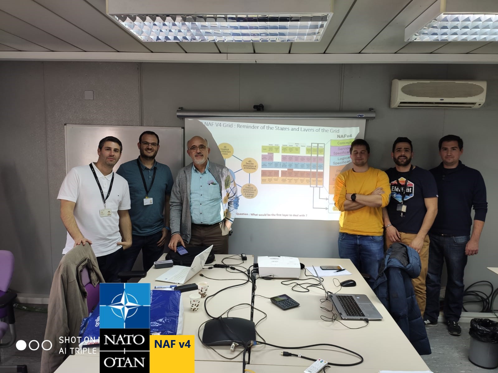
A panorama of MBSE Methodologies : ViTech, State Analysis, RUP SE, Harmony Process (IBM), UAF, NATO NAF v4
A Method based Framework for gathering requirements, system analysis and design
Overview of the UML/SysML diagrams used in requirements gathering, system analysis and design of the System Engineering domain
Gathering Requirements and Transforming them into System Specifications
Making business and system requirements traceable using the SysML requirement diagram
Define the scope of the system composed of functions and use cases that invoke these functions
Techniques in SysML to prototype the behaviour of the System : Model the Life Cycle of the System that orchestrates transitions between its states where functions are triggered
Clarify Requirements using the SysML's Activity and Sequence Diagrams
Acceptance tests and Integration tests : Prepare test cases using scenarios that realize Use Cases and System Functions
Exercices on the Case Study : Model the Initial System Scope and the usage of the system functions on the basis of requirements ; Structure Non Functional Requirements; Complete the scope of the system using relationships between use cases and functions of the system; Model the life cycle of the system / Check out states of the system where functions are to be triggered ; Model the usage scenarios of the system in each state
Transforming System Specifications into Design Level Components
From the UML's Class and Structured Class Diagram to the SysML's Block and Internal Block Diagram : Relationships, Parts, Ports, Interfaces
Refine the Block Diagram using internal blocks to model the Static Aspect of the system
Elaborate the Communication Architecture between Sub-Systems using Parts, Ports and Interfaces
Exercise on the case study : Elaborate the Communication Architecture between Sub-Systems using Parts, Ports and Interfaces
Model the white box Interactions at the design level
Exercices on the Case Study : Refine and Optimise the initial design of the Architecture to better manage evolutions; Model interactions between blocks and Internal Blocks on the basis of design level choices
The concept of Allocation in the System Engineeering
Mapping of Operations onto the Components (Parts) of Blocks
Elaboration of a Parametric Diagram of the System Functions
Exercises on the Case Study : Map the Operations on the Parts and Ports ; Update the Block and Internal Block Diagrams on the basis of design level scenarios ; Establish a parametric Diagram to handle constraints related to a system function.
Other Useful Concepts and Extensions
Change Management of the Requirements and Impacts upon the Existing Functions
Notions of Views and Viewpoints using the ISO/IEC/IEEE 42010 / 2011 standard
Packages and Relationships
Conclusion
The Model Based System Engineering and SysML
Steps of requirement analysis and system specifications in system engineering
Traceability between requirements and the system components
SysML Diagrams used for Requirements Gathering in the Product Requirements Document (PRD)
SysML Diagrams used in the Product Specification Document (PSD)
System Integration and Acceptance Tests of the requirements
Evolution of Architecture Frameworks : DODAF, MODAF, NAF, TOGAF
TOGAF and MODAF Mapping : the Why and the How
Capability Based Planning (CBP) in the System Engineeering
Resources
Notice : The above training-mentoring sessions are conducted interactively using illustrations developed through Requirement Engineering and Modeling tools like the Sparx Systems EA in order to ensure good level of traceability between requirements and underlying solutions.
In case of an on-site session of this course, we can also apply concepts presented during the course to your own case study (and review solutions through an additional scheduled journey if necessary).
After the course, we can also accompany you by reviewing and validating your system engineering solutions depending on your needs.
The logos UML, SysML, MDA referenced on this site are trademarks of the Object Management Group (OMG).
The RUP SE and Harmony processes are a trademark of the IBM / Rational.