GooBiz is a consultancy and training company providing Digital Transformation & System Engineering services across NA, EMEA and currently all other locations including Asia-Pacific in distance training and consultancy
Contact mail : info@goobiz.com or call directly +33 672 3471 25
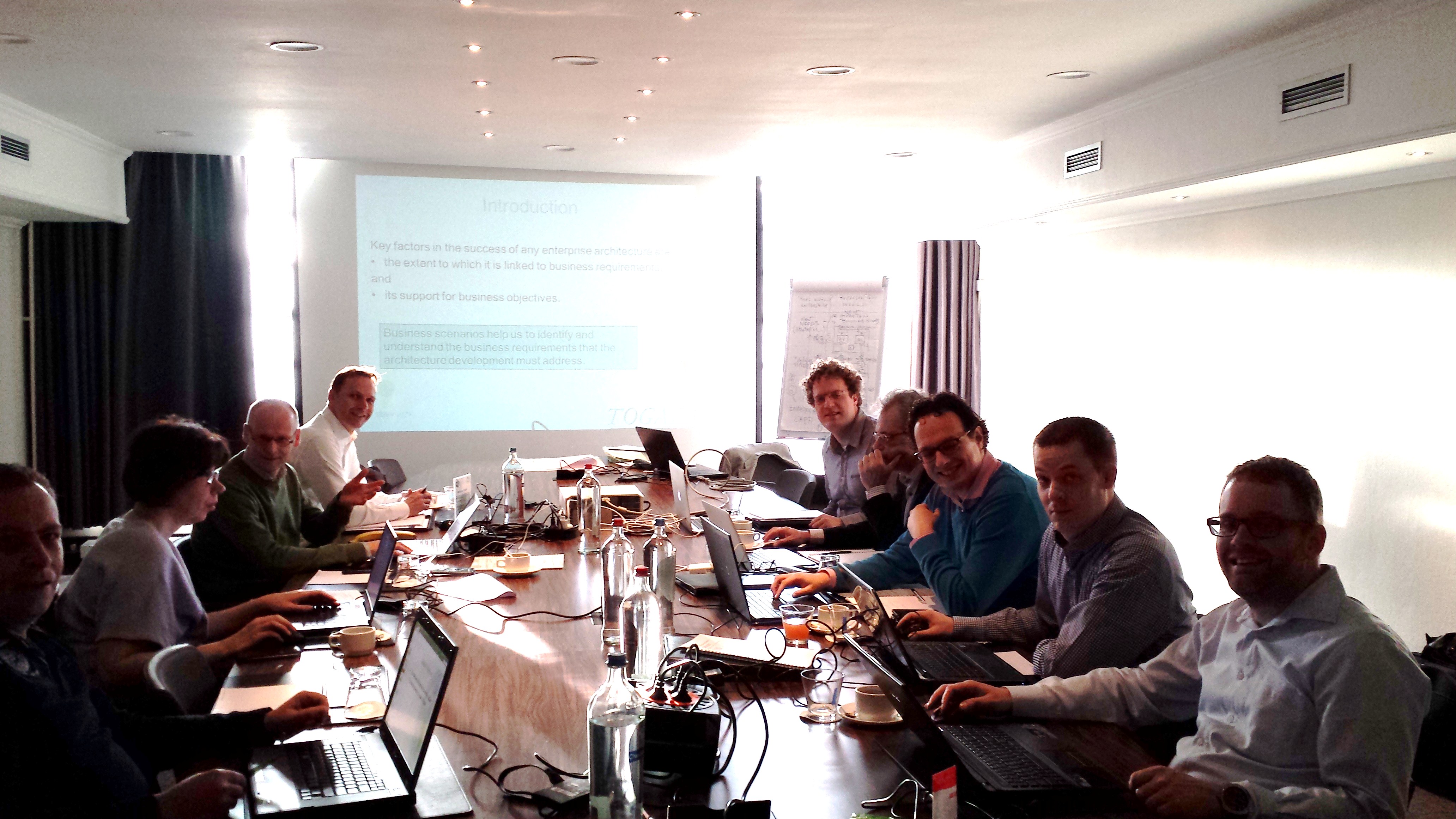
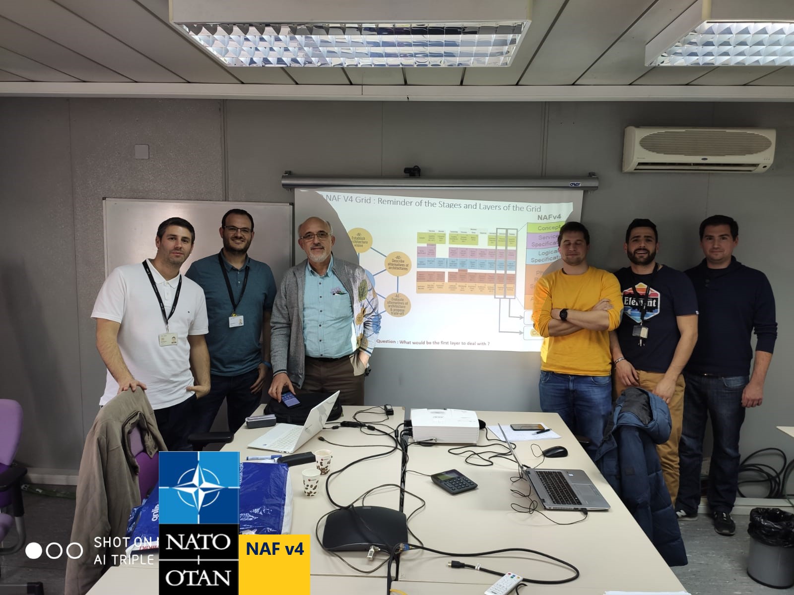
Some feedbacks from our "Putting NATO NAF v4 into Practice for Tactical Adjustment" Training :
Request for a Free Demo about the NATO - NAF v4 training
Contact mail : info@goobiz.com
NATO NAF v4.1 - Architecting the MBSE to enable Strategic and Tactical Adjustments
Aligning Physical Resources with the Enterprise Vision, Strategies, Services and Capabilities and adjust them based on Data Feed-backs

![]() 'NATO NAF v 4.1' is an Architecture Framework standard designed to develop and describe architectures for both military and business sides.
'NATO NAF v 4.1' is an Architecture Framework standard designed to develop and describe architectures for both military and business sides.
This new version of the NAF is based on the OMG's UAF 1.2 Domain Meta-Model (DMM) and the Open Group's ArchiMate 3.2 MetaModels.
We particularly emphasize below on the alignment of Organization Capabilities, Services, Operations, Personnel and Physical System Resources to the Vision, Goals and Strategies as such an alignment becomes facilitated by the new NAF v4 Grid of viewpoints depicted in figure 1 below.
Indeed, NAF v4 brings a well-defined 'grid structure' to align viewpoints from Enterprises Vision, Strategies / Capabilities until Physical Resources. The grid also helps de-risks procurement and enables modular, faster technology insertion and ensures interoperability between different systems through the NATO's Federated Mission Network (FMN) which is one of the primary goals of the NAF v4.1.
While its Subjects of Concern (rows of the grid) focus on different domains from Vision and Capabilities to Physical Systems, its Aspects of Concern (columns of the grid) emphasize on Structural and Behavioral dimensions of architecture elements including their Connectivity, Information Exchange, Constraints and the Roadmap to align underlying subjects.
The behavioral aspects of concern - columns in the middle of the grid contain three aspects namely : Processes, States and Sequences. You can use any of them to define views related to the behavioral specifications of your architecture depending on the context brought by the needs of your stakeholders.
In such a perspective, aligning Process and Sequence views and other ones to 'Desired Effects/States' will help you to avoid wastes in struggling with unnecessary (no productive) modeling.
On the other hand, directing Strategies and Capabilities of the 'Concepts Layer' being based on Desired Effects also help to better align Services, Processes until Roles and Resources of the logical and physical layers.
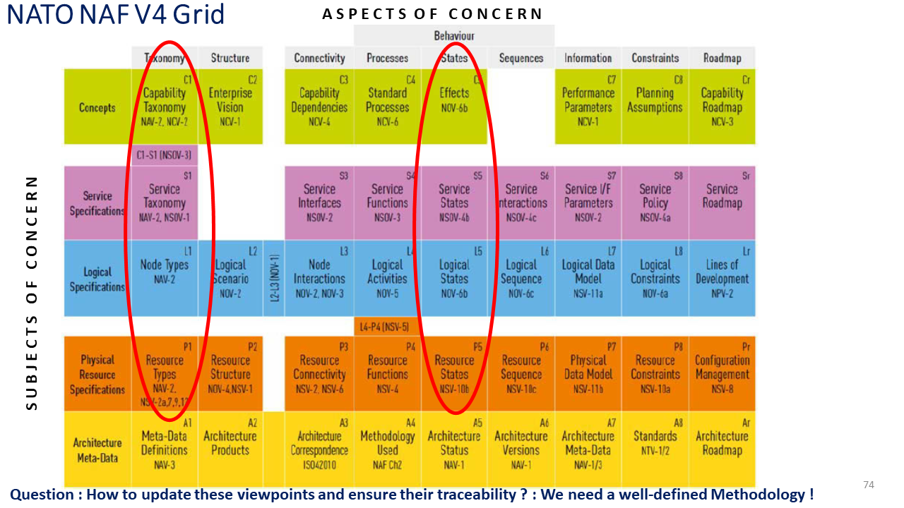
Figure 1 - The NAF v4 Grid of Architecture Viewpoints
Notice that the 'Architecture Meta-Data' has been renamed to 'Architecture Foundation' and the S2- Service Structure Viewpoint has been added to the grid ; some other minor changes occurred in the 2020.07 document of NAF v4 Grid as indicated in Figure 3 below.
Architecture Methodology to feed the NAF v4 Views
NAF v4 defines Methodological Stages similar to TOGAF's ADM phases ; however 'NAF Architecting Stages' do not focus on the sequence in which viewpoints should efficiently be used to ensure an 'architectural coherence' facing changes and saving time in populating the grid :
The figure below shows the Architecting Stages of the NAF V4 Methodology by focusing on its central entity "Managing Architecture Motivation Data'.
The latter makes reference to the OMG's Business Motivation Model (BMM) standard to Manage the Architecture Motivation Data such as Vision, Goals, Influencers (Drivers), Policies and Rules, ... that set the context of 'process adaptation' to major architecture drivers such as interoperability.
Through the interoperability, the goal of NAFv4 is to eliminate operational stovepipes and ensure that data from a satellite, a naval destroyer, and a dismounted soldier can be fused into a single "plug-and-fight", actionable picture for commanders notably by integrating NATO's Federated Mission Network (FMN) Spirals following a clear and traceable path.
In the case of NATO's SAR Operations case study, this ensures the interoperability of the search nodes and rescue nodes combined in a 'single picture of actionable insights' being aligned to Desired Effect and Rules of Tactical C3 and Asset Controller nodes (cf. our proposed NAF v4 training sessions at the end).
Thus, the entire grid of viewpoints are guided by the Architecture Motivation Data Elements indicated in their own categories on the left.

Figure 2 - The NATO NAF v4 - Architecting Stages orchestrated by the Architecture Motivation Data Elements
While being inspired by TOGAF ADM Cycle, the 'Managing Architecture Motivation Data' Entity in the center of NAF v4 methodology helps not only to set the context of 'process adaptation' to major architecture drivers - it also helps to adjust strategies and align underlying views based on data feedbacks that enable a 'plug-and-fight' capability where new systems can be integrated rapidly and reliably into an actionable digital picture.
To truly achieve the Federated Mission Network (FMN) and "plug-and-fight" actionable pictures, the behavioral layers must work as a unified triad:
-
S4 (Functions): What capabilities does the newly plugged asset bring? (e.g., Target Acquisition).
-
S5 (States - The Pilot): What is its current operational readiness and internal logic state? Is it safe and valid to integrate right now?
-
S6 (Interactions): Based on its current S5 state, how does it securely exchange messages to update the actionable digital picture?
The S5 view ensures that the synchronization is not just structurally sound, but behaviorally predictable and resilient under dynamic battlefield conditions.
The figure below depicts on the left some Use Cases of the FMN Pipeline that make reference to Services Views (S4,S5, S6), Architecture Motivation Data (AMD) Central Entity and Logical Views (L) then the corresponding Plug and Fight Actionable Picture Use Cases
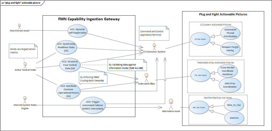
Actors and Use Cases of the FMN (Federated Mission Network) and Single Actionable Plug and Fight System
Architecture Enabled Engineering : Aligning the NAF v4 Viewpoints to Desired Effects / Lessons learned
To provide decision-makers with timely and accurate information using the elements of the architecture, NAF v4 assists you with its "State" and "Information" aspects of the grid to align different architecture viewpoints to Desired Effects (cf.figure 1).
Below you will find some shortcuts to avoid wastes in elaborating no-productive or potentially redundant views in such an alignment :
- First, focus on the Motivational Elements (Vision, goals, … until requirements) using the Vision, Desired Effects, and Constraints (C2, C5, C8) views as well as the target Service taxonomy (S1), Service States (S5) and Service Constraints (S8) views that will provide you respectively with the needed capabilities for Desired Effects and underlying services.
- Then to understand how your existing “Capabilities” and Services need to evolve, prepare a Taxonomy of Capabilities (C1) and Services (S1) views of your existing system (baseline architecture),
- Now, you are ready to realize "Desired Effects" that your organization would like to achieve through the “C5 – Effects” view and analyze impacts from Capabilities till the Physical Resource (P1 to P8) views.
In particular, 'effects' targeted by the C5 view will guide you to focusing directly on the behavioral aspects of the system such as (S4) and (S6) (respectively Service Functions and Interactions) views that need to be clarified for a given "target state" to reach.
Therefore all other underlying Logical and Physical Resource views located within these two behavioral aspects will be aligned to the "S4" and "S6" service views to ensure coherence through the Conceptual, Logical and Physical Data (S7, L7 and P7) views.
Some complementary recommendations to ensure Architectural Coherence
The figure below depicts the 'Motivational Alignment' of the NAF v4 grid views based on the Motivation Data Elements (cf. figure 2) that are summarized using ArchiMate langage notations (from Drivers, Assessments and Goals until Constraints) on the right.
Being fueled by such a 'Motivational Data', the two small arrows depicted on the left of the NAF grid that are originated from "Desired States/Effects " indicate aspects of Capabilities, Services and underlying Logical and Physical Resource views that need to be aligned with these "Target States or Effects" to reach.
Such a 'Strategic alignment' aims to ensure not only the coherence of the Architecture Building Blocks vertically ; but it does also contribute to populate the grid through appropriate views being aligned to these desired states (Horizontal Coherence) through subjects of concern...

Figure 3 - Correspondences between NAF V4 Grid and ArchiMate Layers aligned with the Business Motivation Aspect depicted on the right
Tips to ensure the Strategic and Tactical Alignment
Tip 1 : The alignment of the subjects of concerns (horizontal layers) of the grid with 'Desired Effects' that your organization would like to achieve aims to provide decision makers with accurate information collected through these layers and serve in realizing a dynamic "gap analysis" between existing and target desired states.
Therefore, it does not only assist you initially in preparing the roadmap of incremental capabilities using the capability roadmap (Cr) view but also helps in adjusting them through 'desired effect based data' that need to be collected from layers (cf. the Data-Driven Strategic Alignment using the NAF v4 schema depicted in figure 5).
Tip 2 : The gap analysis helps to fragment capabilities into 2nd or 3rd level granularities to ensure traceability using the C1-S1 (Capability to Service Mapping ) view to match the reality of "units of works" of services that need to be provided to their user/consumers.
Tip 3 : In addition, expressing both capabilities and services being based on 'Desired Effects' and aligning physical functions based on logical activities through the (L4-P4) bridge viewpoint helps to ensure alignment of physical resources to evolution of strategies due to changes on drivers.
An excerpt from some of these views referenced within NAF v4 Grid are provided below from the Strategic (Concept) Viewpoint to the Resources Viewpoint with an alignment being based on the Architecture Motivation Data (outlined in Figure 2 above).
Such an alignment allows you to update elements of the architecture in coherence according to 'Desired Effects' you want to achieve for your Organization and System Architectures.
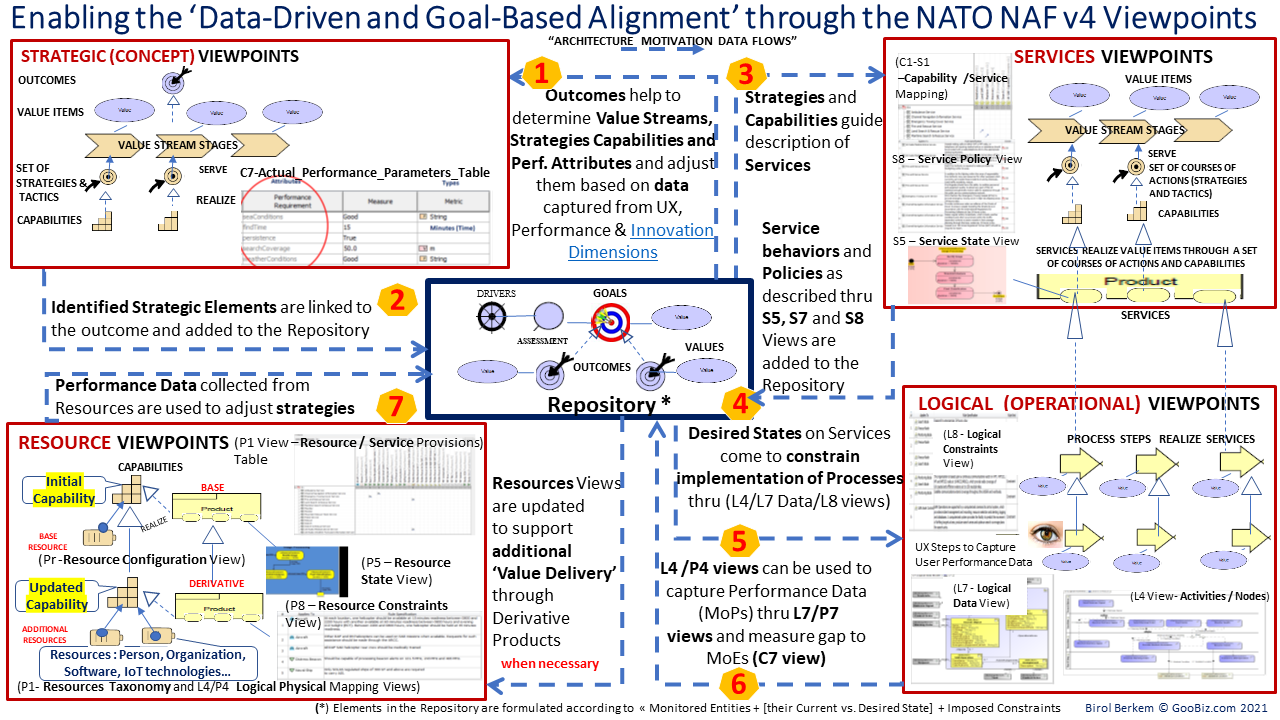
Figure 4 - Orchestration of NAF v4 Views from Strategies till Resource Configurations based on the Architecture Motivation Data (cf figure 2 for other stategic elements to add to the center of the figure)
Summary
The figure below outlines a summary of high-level steps to align horizontally and vertically the Aspects of Concerns of the NAF V4 Grid to 'Desired Effects'
Steps 1 and 2 below help to feed respectively the 'Motivation Data' (Goals, Strategies, Policies, Rules) based on the Business Motivation Model then describe and set views of the NAF v4 grid according to the Vision and Goals.
The Step 3 focuses on the necessary alignment of the Grid of Views to Desired Effects until the Physical Resource Layer.
Finally Step 4 allows to collect data feed-backs such as the Measures of Performances (MoPs) from the Physical layer to adjust Value-Delivery on an Insight basis.
These Data Feed-backs need to be assessed by Step 5 to adjust strategies before initiating a new alignment cycle of the Architecture Views of the Grid (through a new sequence of Steps 2,3 and 4).
Such an adjustment enables a 'plug-and-fight' capability where new systems can be integrated rapidly and reliably into the actionable digital picture.
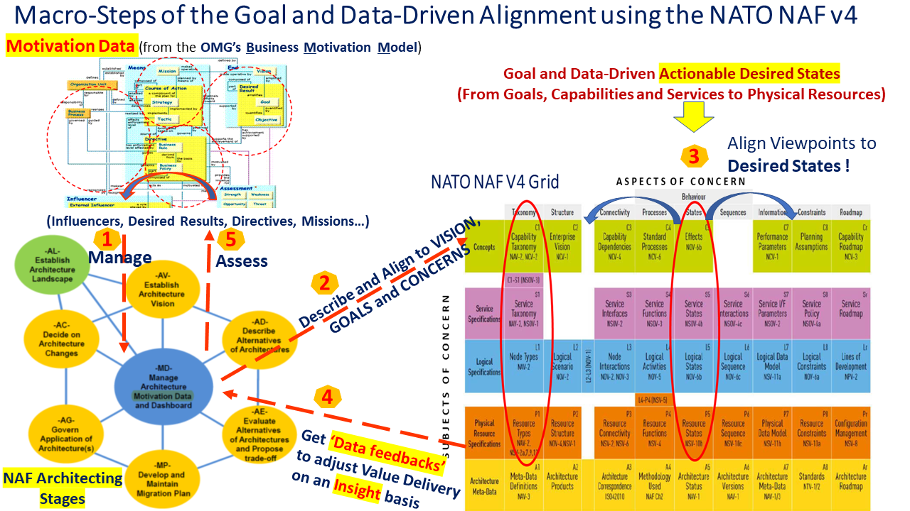
Figure 5 - Data-Driven Strategic Alignment using the NATO NAF v4 Architecting Stages and its Grid of Architecture Viewpoints
Complementary information about the NATO NAF v4 and the end-to-end alignment through the "architecture enabled decision-making" based on feedbacks captured from Physical Resources are provided in the following training courses :
- Putting the NAF v4 into practice on an end-to-end case study using Sparx tools (optionnaly using the Sparx NAF V4 Plug-in)
--
Last updated by Birol Berkem, Ph.D, April 20th, 2026 - GooBiz, Paris

This work is licensed under a Creative Commons Attribution-ShareAlike 4.0 International License.
Related Standards :