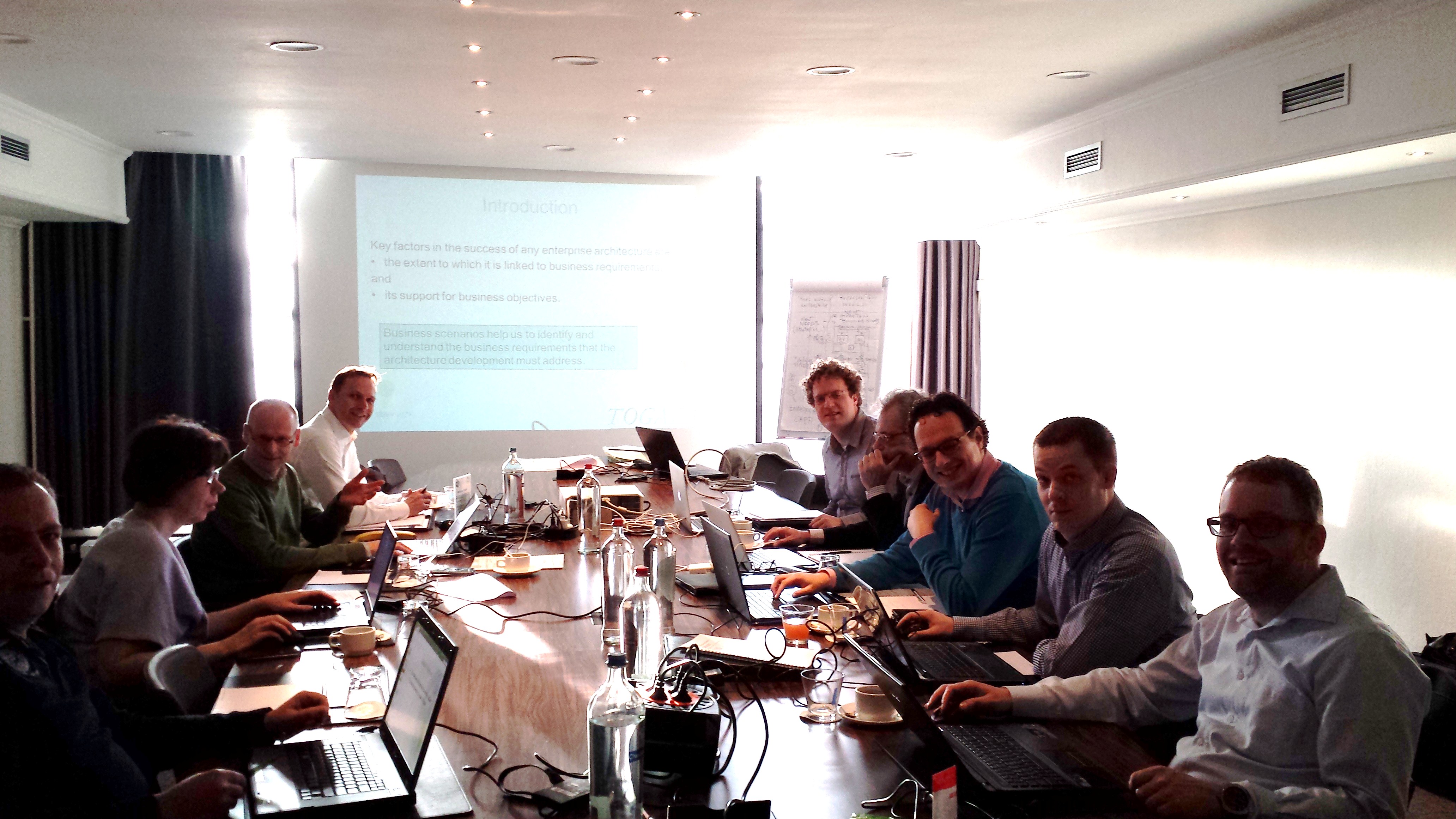
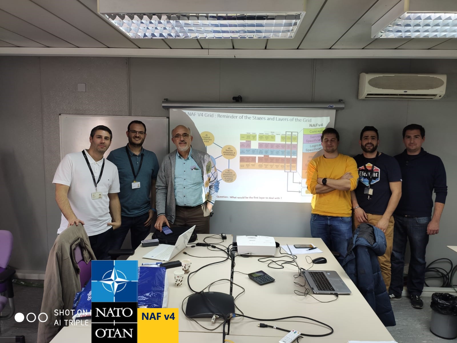
GooBiz is a consultancy and training company providing Digital Transformation & System Engineering services across NA, EMEA and currently all other locations including Asia-Pacific in distance training and consultancy
Contact mail : info@goobiz.com
Some feedback from our "Putting NATO NAF v4 into Practice for Tactical Adjustment" Training :
Request a Free Demo of the NATO - NAF v4 training
Contact mail : info@goobiz.com
NATO NAF v4.1 - Introduction to NATO Architecture Framework
Bridging strategic vision with operational execution

 'NATO NAF v 4.1' is an Architecture Framework standard designed to develop and describe architectures for both military and business sides.
This new version of the NAF is based on the OMG's UAF 1.2 Domain Meta-Model (DMM) and the Open Group's ArchiMate 3.2 MetaModels.
NATO NAF v4 establishes the bridge from strategic vision to operational execution throughout two main components : the NAF v4 Grid of Viewpoints and the NAF v4 Methodology outlined below
The NAF v4 Grid of Architecture Viewpoints
The NAF v4 Grid of Viewpoints is organized using two dimensions : Subjects of Concerns (Rows) and Aspects of Concerns (Columns)
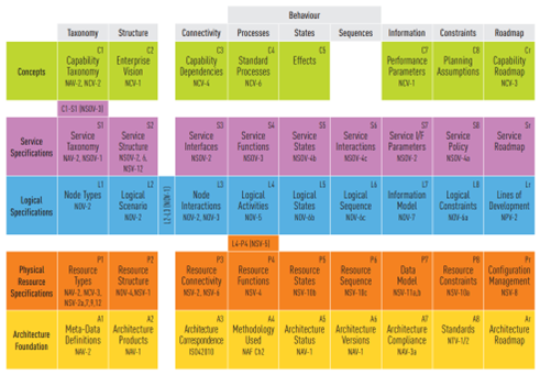
Figure 1 - The NAF v4 Grid of Architecture Viewpoints
The Subjects of Concerns (Rows of the Grid) are :
-
C – Concepts (Strategic Row): Focuses on high-level enterprise goals, vision, and strategic intent. It captures what the enterprise fundamentally exists to do (such as Capabilities, Enduring Tasks, and doctrine-level Standard Processes) without specifying operational implementations or technical solutions.
-
S – Service Specifications (Service Row): Defines the published service contracts, interfaces, and service-level agreements (SLAs) through which capabilities are delivered. It acts as the functional bridge between strategic needs and operational/system execution by specifying what services are provided and consumed independently of specific implementations.
-
L – Logical Architecture (Operational / Solution Row): Describes the operational domain in solution-independent terms. It models how operational actors and nodes interact, detailing operational activities, logical node structures, information flows, and operational state transitions required to fulfill missions.
-
P – Physical Resource Architecture (Implementation Row): Specifies the concrete physical resources, systems, software, hardware, facilities, and personnel configurations that realize the logical architecture. It captures with what real-world assets the architecture is implemented and deployed.
The Aspects of Concerns (Columns of the Grid) are :
-
1 – Taxonomy: Defines the catalog, classification, and hierarchy of elements within a layer (e.g., Capability Taxonomies in C1, Service Taxonomies in S1, Resource Taxonomies in P1). It provides the standardized vocabulary and building blocks for that perspective.
-
2 – Structure: Focuses on the structural decomposition, organization, and composition of entities and their relationships (e.g., Enterprise Vision/Enduring Tasks in C2, Logical Nodes in L2, Systems/Resources in P2).
-
3 – State: Models the dynamic behavior, states, and state transitions of entities over time (e.g., Service State Models in S3, Operational Node States in L3, Physical Resource States in P3).
-
4 – Processes: Captures the behavioral workflows, activities, and operational flows (e.g., Standard Processes in C4, Logical Activities in L4, Physical Resource Processes in P4).
-
5 – Connectivity: Describes the interfaces, exchanges, and connectivity between entities (e.g., Operational Information Exchanges in L5, Physical Interfaces/Resource Connectors in P5).
-
6 – Data & Information: Models the data structures, information models, and exchange definitions (e.g., Operational Information Models in L6, System Data Models in P6).
-
7 – Technology / Governance: Focuses on the governing rules, standards, constraints, and technological baselines (e.g., Standards and Rules in L7/P7).
-
8 – Roadmap / Evolution: Maps the temporal evolution, deployment timelines, and transition plans of elements over time (e.g., Capability Roadmaps in C8, System Deployment Timelines in P8).
The NAF v4 Methodology : Architecting Stages to populate the Grid
The NAF v4 Methodology is mainly composed of Architecting Stages that focus on what to do in each stage to develop the architecture and viewpoints of the grid that are concerned by these stages.
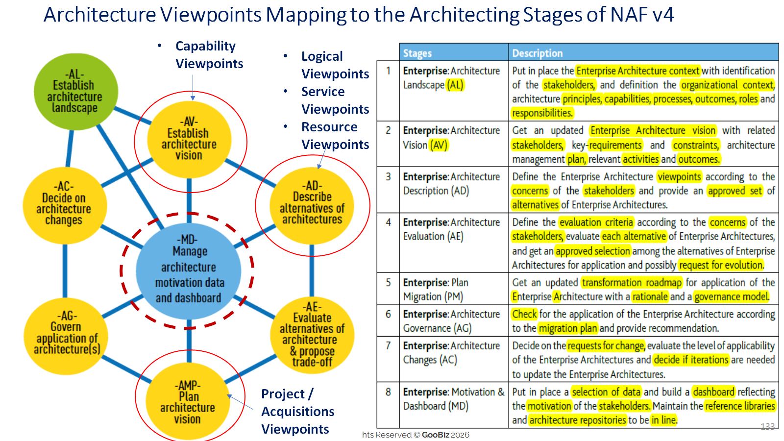
Figure 2 - Stages of the NAF v4 Architecture Development Methodology orchestrated by the 'Manage Architecting Motivation Data' - central entity of the Architecture Development Methodology
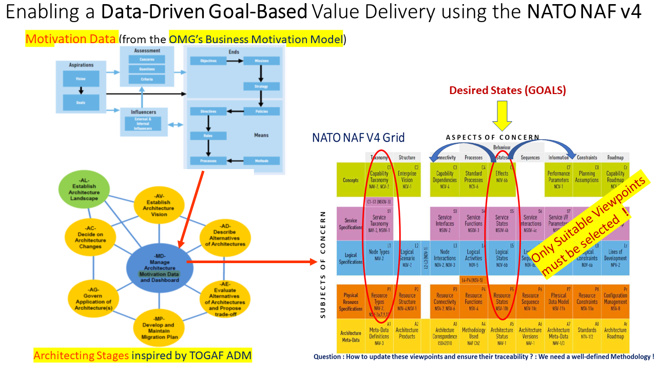
The figure below outlines the Strategic and Data-Driven Alignment of the Grid with the Architecting Stages on the left.
The 'Manage Architecting Motivation Data' - central entity of the Architecture Development Methodology is based on the elements of the OMG's Business Motivation Model (BMM).
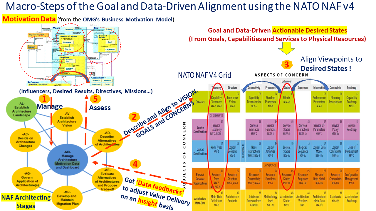
Figure 3 - Strategic and Data-Driven Alignment using the NATO NAF v4 Architecting Stages and its Grid of Architecture Viewpoints
The steps are as follows :
Map Drivers, Goals, Policies, and Constraints using the Business Motivation Model (BMM) central entity to set the rules for process adaptation.
Build C1 (Capability Taxonomy) and S1 (Service Taxonomy) views to establish a clear gap analysis between legacy baselines and required target states being assisted by the C2 (Vision) and C5 (Desired Effects) views.
Capture Measures of Performance (MoPs) from active physical assets for assessment.
Adjust dynamically high-level strategies and refine capability roadmaps (Cr) down to Project roadmaps (Lr).
Detailed information on the NATO NAF v4.1 framework with an end-to-end alignment are provided in the following training courses.
They cover not only the top-down alignment but also the bottom-up adjustment of Tactics, Capabilities, Services, Processes and Resources on the basis of Data-Feed-backs captured from the Physical Resource Layer (Steps 4 and 5).
These courses help you understand how to bridge the Strategic Vision with Operational Execution using the Sparx EA and the Sparx NATO NAF v4 Plug-in for your Defense Projects
Key Outcomes for Your Defense Projects
-
Eliminate Operational Stovepipes: Fuse data from satellites, naval assets, and dismounted personnel into a single "plug-and-fight" actionable operational picture.
-
Streamline FMN Integration: Accelerate compliance with NATO’s Federated Mission Network (FMN) spirals.
-
Eliminate Modeling Waste: Focus specifically on Desired Effects (C5) and Service Behavioral Triads (S4, S5, S6) to avoid redundant diagramming.
-
De-Risk Procurement: Ensure modularity, rapid technology insertion, and multi-domain interoperability across all procurement stages.
Some of these outcomes are outlined in the 2nd part of this article that focuses on Strategic Alignment and Tactical Adjustment of the Model Based System Architecture.
--
Last updated by Birol Berkem, Ph.D, September 19th, 2026 - GooBiz, Paris

This work is licensed under a Creative Commons Attribution-ShareAlike 4.0 International License.
Related Standards :